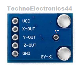
ADXL335
Accelerometer
Module
ADXL335 is an analog sensor and also called a triple-axis accelerometer.
This device can measure the acceleration with a minimum of a full-scale of ±3g.
It can measure the static acceleration in angular tilt sensing applications and
dynamic acceleration in shock, motion, vibrations. It is compatible with
Microcontrollers. It is designed with the structure of the MEMS technology,
scroll down for MEMS technology.
Model number: ADXL335
Output: Analog signal
Other names: Accelerometer, MEMS, Vibrator sensor, GY-61
Other related modules: MPU6050, ADXL345, ADXL357, ADXL326.
 |
| ADXL335 |
What
is g | g-force
It is the measurement of the force per unit mass. “g-force” of 1-g equal to the conventional value of gravitational acceleration on Earth, 1-g force is equal to 9.8 m/s2.
MEMS
| what is MEMS
MEMS-Micro Electro-Mechanical System is designed with a micromachined
structure built on a silicon wafer. This structure is designed with
poly-silicon springs, that allows to make internal deflections at the time of
acceleration is applied on the axis. The change in deflections will affect the
internal capacitances between the plates that lead to change in output voltage.
So this process of change in capacitance will
convert into analog output voltage at x-axis, y-axis, z-axis.
Pin
Configuration
|
Vcc |
Supply
voltage positive pin |
|
GND |
Supply
voltage negative pin |
|
X-out |
Analog
output(X-Axis) |
|
Y-out |
Analog
output(Y-Axis) |
|
Z-out |
Analog
output(Z-Axis) |
|
ST |
Self
test pin |
 |
| ADXL335-Pinout |
 |
| ADXL335-Pinout |
Features
- Model number: ADXL335.
- Output: Analog
- Type: 3-axis
- Inbuilt voltage regulator- 3v3
- RoHS/WEEE lead-free compliant
Technical
specifications
Operating voltage(Vs): 1.8v to 3.6v
Supply-current: 350uA at 3v
Turn ON time: 1ms
Operating temperature range: -40 ̊C to +85 ̊C.
Measurement range: ±3g
Sensitivity: 300mv/g at g=0, Vs=3v, T=25̊̊ C
Output voltage: 1.5v at g=0, Vs=3V.
For more details refer to Datasheet , you will find below
Factors
affect the Output voltage
The analog output voltage depends on the three
factors
Supply voltage
G-vale (up to ±3g)
Noise factor.
Supply
voltage
The output voltage is proportional to the supply
voltage. At Vs=3.6v the output sensitivity is 360mV/g, at Vs=2v the output
sensitivity is 195mV/g.
g-value
At 0-g the output voltage is equal to Vs/2 at all
supply voltages as per Datasheet.
Noise
factor
The
noise density decreases as supply voltage increases, At VS = 3.6 V, the X-axis and Y-axis
noise density is typically 120 μg/√Hz, and VS = 2 V, the X-axis and
Y-axis noise density is typically 270 μg/√Hz.
Arduino
with ADXL335 | Arduino with MEMS-Accelerometer
ADXL335 is compatible with microcontroller and it
provides the analog output, for calibrating the analog data we have to use the
ADC-analog to digital converter. Arduino has an inbuilt 10bit-ADC it provides the minimum value is ‘0’ and the maximum value is 1023 so Arduino ADC provides 1024
discrete numbers.
Arduino Uno has
6-channel ADC from A0-A5 and ADXL335 has 3-analog outputs
(X-axis, Y-axis, Z-axis).In our design, we require 3-ADC channels, 5V, GND pins
of Arduino.
ADXL335
Interface with Arduino connections
|
ADXL335 |
ARDUINO UNO |
|
Vcc |
5v |
|
GND |
GND |
|
X-out |
A0 |
|
y-out |
A1 |
|
Z-out |
A2 |
|
ST |
No
connection/GND |
Note
: Here
Vcc is connected to 5V because it has an inbuilt voltage regulator-3v3
, ADSL335 operating voltage is 3.3v.
Warning:
For
self-test purpose you have to connect at Vs (1.8v-3.6v), if the voltage at
self-test pin crosses 3.6v it may cause to damage the device
Circuit
diagram
 |
| ARDUINO WITH-ADXL335 |
Arduino Code For ADXL335
Circuit
Working
From the above circuit, we can conclude that x-axis, y-axis, the z-axis is connected to analog pins of Arduino, the voltage at the analog pins(A0,A1,A2) will be converted into readings by using analog Read(x_axis) gives the readings at A0(x_out), analog Read(y_axis) gives the readings at A1(y_out), analog Read(z_axis) gives the readings at A2(z_out). These readings are printed on the Serial monitor using “Serial.print”.
Datasheet
Applications
- Mobile devices
- Gaming systems
- Disk drive protection
- Image stabilization
- Sports and health devices


0 Comments