LCD(16x2)
LCD pin diagram
 |
| 16x2 LCD Module |
 |
| LCD-Pin-Diagram |
Pin description
|
1 |
Vss |
Ground |
|
2 |
Vcc/Vdd |
5v(Positive terminal) |
|
3 |
VE |
Contrast
(brightness adjustment) |
|
4 |
RS |
Register Select
(to select Data mode or command mode) |
|
5 |
R/W |
Read / Write
Operation |
|
6 |
EN |
Enable |
|
7 |
D0 |
Data pin 0 |
|
8 |
D1 |
Data pin 1 |
|
9 |
D2 |
Data pin 2 |
|
10 |
D3 |
Data pin 3 |
|
11 |
D4 |
Data pin 4 |
|
12 |
D5 |
Data pin 5 |
|
13 |
D6 |
Data pin 6 |
|
14 |
D7 |
Data pin 7 |
|
15 |
A |
Anode (Backlight
positive terminal) |
|
16 |
K |
Cathode (Back
light negative terminal) |
Power supply pins
- Vdd – is the power supply positive pin
- Vss – is the power supply negative pin
- A – Anode terminal (positive terminal of Back Light LED)
- K – Cathode terminal (Negative terminal of Back Light LED)
Contrast pin
- Vee – to adjust the Backlight LED brightness (connect 10k pot)
By adjusting the voltage across this pin brightness will be
adjust.
Control pins
- RS – Register select, it is useful to select the command mode or data mode of operation
- RS=0 for command mode, whereas RS=1 for data mode.
- R/W – To perform the Read and write operation (Write Operation is an active LOW signal)
- En –Enable pin, we can assign the instructions by triggering the Enable pin.
Data pins
D0-D8 = Usually it has 8-data pins. It supports two modes of
operations.
- 8-bit data mode
- 4-bit data mode
You can select any one of the modes by using the commands,
and there is no effect on performance.
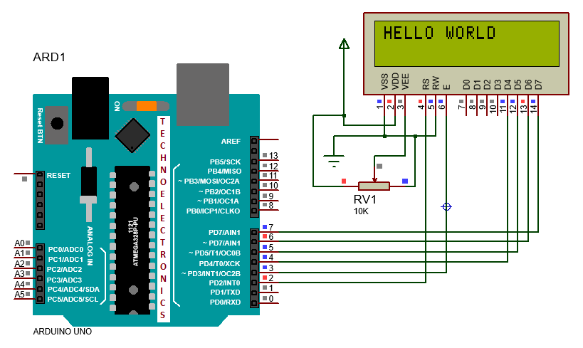
LCD interface with Arduino Uno
Now we design in 4-bit data mode
LCD-Interface with Arduino
- VSS, R/W, K (1,5,16) pins are connected to Ground
- Vdd, A (2, 15) pins are connected to POWER SUPPLY positive terminal.
- Vee is connected to 10K Potentiometer
- RS, EN, D4, D5, D6, D7 Pins are connected to any data pins but try to maintain them in order.
 |
| LCD_Arduino_Interface |
NOTE: In the above circuit LCD 15,
16 pins are not shown, so you should take care of that connection
How to write a program for LCD module
- lcd.write( ) – Print the Character.
- Ex: lcd.write('M');
- lcd.clear() - clear the display
- lcd.Display() - Turn ON the display
- lcd.begin ()- setup the LCD number of Rows and columns.
- Ex: lcd.begin(16,2);
- lcd.print() – Print data
- Ex: lcd.print("Mahesh");
- lcd.NoDisplay() - Turn OFF the display
- lcd.setCursor() – Set the Cursor position
- Ex: lcd.setCursor(3,1);
- lcd.noBlink() – Cursor blink.
- lcd.blink() – cursor No blink.
- lcd.cursor() - Turn on the cursor
- lcd.noCursor() - Turn off the cursor
- lcd.leftToRight() - go left for the next letter
- lcd.rightToLeft() - go right for the next letter
- lcd.home() - go to (0,0)
- lcd.scrollDisplayLeft() - scroll one position left
- lcd.scrollDisplayRight() - scroll one position right
- lcd.autoscroll() - set the display to automatically scroll
- lcd.noAutoscroll() - turn off automatic scrolling
NOTE:
All the above
functions are predefined and case
sensitive.
Program 1: Print “HELLO WORLD”
Implementation Steps
- Make the hardware connections properly.
- Include the “LiquidCrystal.h “ header file
- Initialize the LCD interfacing pins corresponding to the hardware
- lcd.begin()- setup the LCD number of Rows and columns.
- lcd.setCursor() – Set the Cursor position, where you want to print data.
- Example: lcd.setCursor(2,1) – data print from 2nd column, 1- Row lcd.setCursor(4,0) – data print from 4TH column, 0- Row
- lcd.print(“HELLO WORLD”) – Print data “HELLO WORLD”.
Code
program2: print alphabets and numbers
 |
| LCD_Arduino_Interface |


1 Comments
thnku @ M@HESH
ReplyDelete