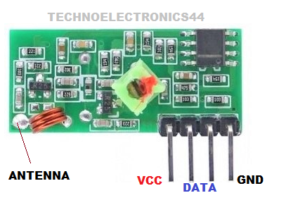
RF Receiver Module is the wireless communication
module, which operates at 433MHz signal and it is the data transmission used for short-distance communication. For wireless communication,
we need a Transmitter and receiver module.
Before reading this topic once refer RF-Transmitter Module
In this tutorial, we
will discuss the Receiver module :
RF: Radio
Frequency
Model number: FS1000A
Other names: 433MHz RF
Receiver, RF-Receiver, RF-Rx Module.
Other similar devices: 315 MHz, nrf24L01
 |
| RF-RECEIVER |
Pin configuration
|
VCC |
Power
supply positive pin |
|
GND |
Power
supply negative pin |
|
DATA |
Data
received pin |
|
ANT |
Antenna |
|
DATA |
Data
received pin |
Note: Two DATA pins are the same. You can use any of the pins, or simply you can short the two pins.
Features
- Modulation Technique: ASK-Amplitude shift keying
- Circuit model: saw resonator
- simplex communication
- serial data receiving.
- The minimum power supply is required to operate
- Low cost
- Without an antenna, we can send data up to 1-meter
Technical Specifications
- Model Number: FS1000A
- Operating voltage: receiver: 3-12v
- Operating frequency: 433.92 MHz
- Turn ON time: min-10ms, typical-20ms.
- Data rate: typical-1kbps, max-3kbps.
- Communication range: 70mts
Where to use 433MHz RF Module
It is a short-range
wireless communication, based on this specification we will use this module where we need to design a short-range wireless applications such as
following:
Example-1 For suppose we want to unlock the car
door remotely so, we can design this application using our smart RF
module.
Example-2 Design of remote toy cars using wireless
control
Example-3 wireless water level indicator In such applications, if the distance between the alarm indicator and the water tank is very less, then we can go for wired communication but in some buildings it is not possible to make 50mts of wire and arrangement in that applications it is better to implement wireless communication.
How RF Receiver Module Work
It Receives the data over the air(free space) with the data rate of 3kbps speed. It consists of RF tuned circuit and a couple of op-amps required to amplify the received carrier signal from the transmitter module. The amplified signal further fed to the Phase lock loop which enables the decoder to “lock” on to the digital bits, which gives better-decoded output
How
to use 433Mhz RF Receiver module | Arduino with 433Mhz RF Receiver Module
RF Module receives data
through serial transmission i.e bit by bit. You can interface this module
directly with any of the electronic switching devices other-wise you can
interface with microcontrollers.
Note: Here I’m giving 5V power supply
Arduino
Interface with RF Receiver
|
VCC |
5V-Arduino |
|
GND |
GND-Arduino |
|
DATA |
8-Arduino |
|
ANT |
Connect
to 10cm wire |
Circuit
diagram
 |
| ARDUINO RF-RECEIVER -CIRCUIT |
Circuit
Explanation
In the above circuit, we
apply the 5v dc supply using Arduino as shown in the circuit diagram,
According to the circuit when the switch is in closed state at the
transmitter side, Receive Module gets LOGIC-0 and when switch is in open state at the transmitter side, Receiver
gets LOGIC-1,
So we can say that when
the input switch is closed state RF Transmitter module sends
LOGIC-0 to the receiver when the switch is in an open state RFTransmitter sends LOGIC-1 to the receiver part.
Datasheet
Applications
- Remote controls
- Automation systems
- Wireless security system
- Short distance communication (simplex)
- Industrial wireless security alarm systems


0 Comments