IR SENSOR MODULE
IR sensor module is used to measure motor speed, obstacle
detection, color detection.
The circuit formation of IR LED (IRtransmitter LED and IR Receiver LED) is known as IR
sensor module.IR sensor module consists of IR LED,
LM358 (comparator), Preset, LED light indicator.IR sensor module emits
the Infrared light using this IR transmitting LED, the wavelength of IR light is 700nm-1nm.IR light wavelength
invisible to the human eye so you can observe this light from the mobile
camera. The range of IR light is from centimeters to feet that
depend on the type of the IR sensor module.
For example short range IR sensor module, long-range IR sensor module.
 |
| IR-SENSOR-MODULE-PINOUT |
Type : short range IR sensor module(up to 20cm).
Other
names: Photo Diode, Optoelectronic component,
IR-LED, IR-Transmitter, IR- Receiver, IR-Pair, IR-Module, IR proximity sensor.
Other related devices
IR module, TSOP1738, HSDL-4260, SIR204C
|
1 |
Vcc |
Battery
positive pin |
|
2 |
Data
(D0) |
Digital
data output |
|
3 |
Data
(A0) |
Analog
data output |
|
4 |
GND |
Battery
negative pin |
Note:
some
IR sensor modules have only three pins Vcc, Gnd, D0.
- Digital and analog output signal
- Detection distance: 2 ~ 20cm
- Detection angle: 35 ° Degree
- Comparator chip: LM393/LM358
- Adjustable detection distance range via potentiometer/Preset:
- Clockwise: Increase detection distance
- Counter-clockwise: Reduce detection distance
Technical specifications
- Working voltage: 3 - 5V DC
- Distance: 2-20cm
- Output type: Digital switching output (0 and 1) and Analog output
- 3mm screw holes for easy mounting
- Board size: 3.2 x 1.4cm
How the IR Receiver LED | Photo Diode works
It is the Receiver part of the IR sensor
module. IR Receiver LED operates in Reverse bias condition
that means current flow will increase in reverse bias condition. When the
light falls on the receiver part the IR Receiver will start
conducting and current flow will increase, so the current flow will depend on the
amount of light intensity that falls on the receiver part.IR receiver LED is
coated with black color because of black color absorbs the high amount of light
intensity.
Preset
Preset is used to adjust the sensitivity of the IR
sensor module.
For example: By default, the sensor
detects the obstacle in the range of 10cm only so if you want to
change (either increase or decrease) the obstacle detection range of the sensor
you can vary the preset manually and fix it at a certain position.
Preset is used to vary the obstacle detection
range of the IR sensor module.
Working
of IR sensor module
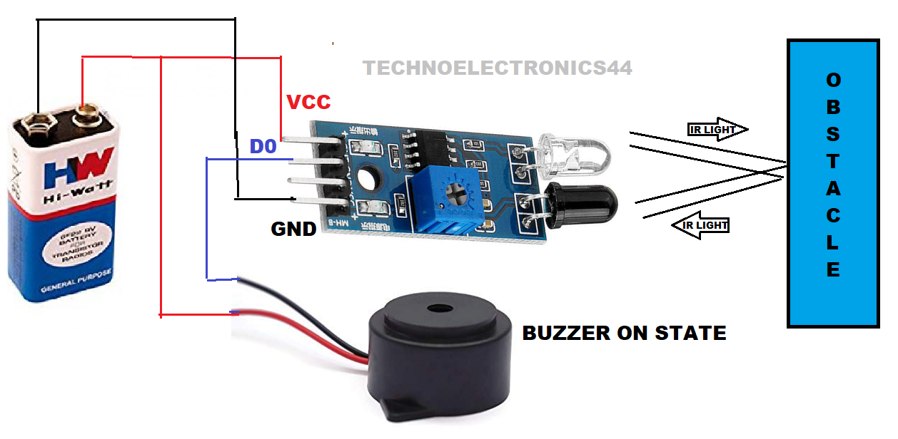
In this circuit, the default (No IR light falls on the Receiver-No obstacle) the output is LOGIC-1 when IR Light falls on the receiver, the output will transition to LOGIC-0.
Default-No
obstacle
 |
| IR-SENSOR-MODULE-CIRCUIT |
When there is no obstacle in front of IR LED, No IR light falls on the
Receiver
The output is LOGIC-1
Obstacle presence
 |
| IR-SENSOR-MODULE-CIRCUIT |
Here obstacle is present
in front of the IR sensor module then the IR light reflects and falls on the Receiver LED.
The output is LOGIC-0.
Note: The object should have white color, then
you can get efficient output because white-color is
perfectly reflect the IR-signal (The object should have an IR signal reflecting
nature)
Note
: The
output of the IR sensor module depends on the sensor module circuitry, by
default it can give either Logic-0 or LOGIC-1, so you need to check using
multimeter. Most of the IR sensor modules are work as discussed above.
Arduino with IR sensor
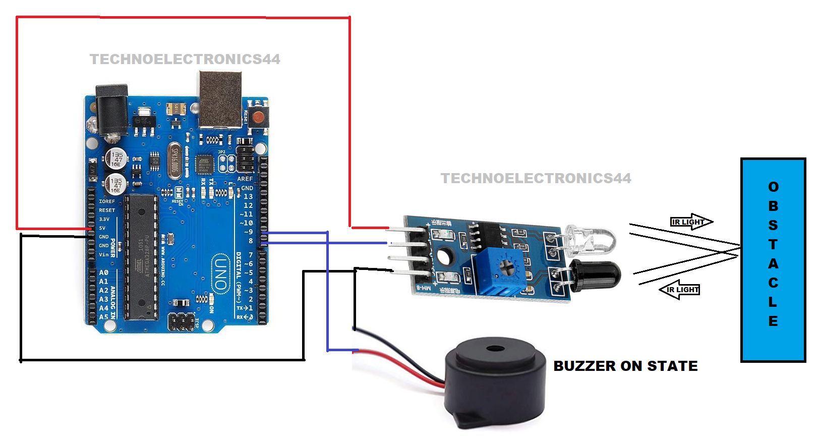
IR sensor module has four pins Vcc, Gnd, Digital
output(D0),Analog output(A0).
IR
sensor module
Vcc is connected to a 5V pin of Arduino
GND is connected to the GND pin of the Arduino
D0 pin is connected to any digital data pin (8) of
Arduino
Buzzer
The buzzer has two pins positive terminal and negative
terminal.
Note:
buzzer
is an interface with positive logic
The positive pin of the buzzer is connected to any digital
pin of Arduino
The negative pin is connected to the GND of the Arduino
CIRCUIT
 |
| ARDUINO-WITH-IR-SENSOR |
CIRCUIT WITH OBSTACLE
 |
| ARDUINO-WITH-IR-SENSOR |
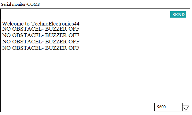
 |
| ARDUINO WITH IR OUTPUT WINDOW-NO OBSTACLE |
Working principle
When there is
no obstacle IR sensor module sends LOGIC-1 to Arduino, So Arduino identifies
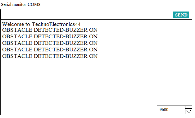
there is no obstacle. if there is any obstacle within the range the IR sensor module sends LOGIC-0
to Arduino, then Arduino identifies there is an obstacle detected, and Arduinoturn ON the buzzer.
Note:
when
the buzzer is turned ON/OFF is completely depends on the Arduino program.
 |
| ARDUINO WITH IR OUTPUT WINDOW-OBSTACLE |
DATASHEET
APPLICATIONS
- Motor speed measurement
- Obstacle detection
- Contactless temperature measurement
- Counting machines
- Security systems because of IR signals are invisible to human eye
- Cameras


2 Comments
thank you @LED LIGHT EXPERT
ReplyDeletethank you@ BIRDUV
ReplyDelete